PCB board end headers with two mounting orientations often confuse automotive engineers. This article contrasts horizontal and right angle auto connectors in layout, reliability, and application scenarios. We provide clear selection standards to help you optimize space in your EV and power tool control modules, effectively reducing engineering design risks.
Basic Structural Definition of Two PCB Auto Headers
Horizontal PCB Automotive Header
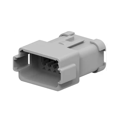
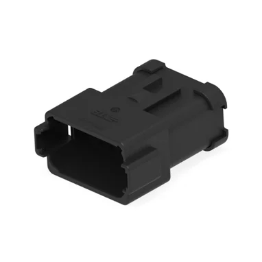
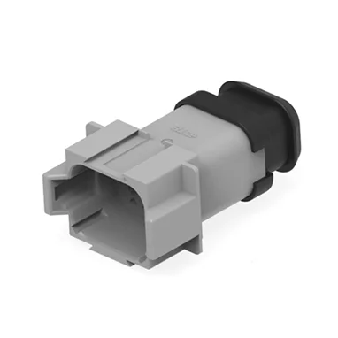
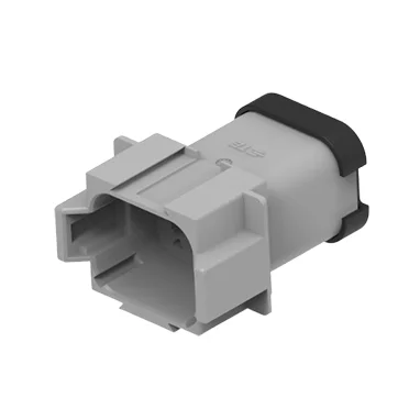
Horizontal headers are designed with pins running parallel to the PCB plane. This flat, board-mounted configuration is common in modules where vertical space is not a limiting factor. For instance, GVEI’s compatible horizontal headers are widely used in automotive electronics where a low lateral profile is required to facilitate stable, long-distance straight wiring.
Right Angle (90°) PCB Auto Header
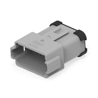
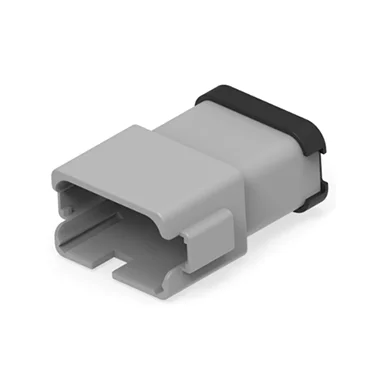
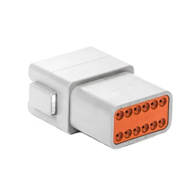
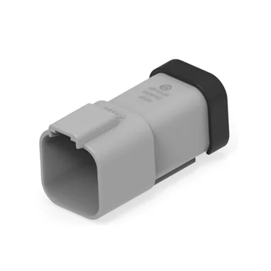
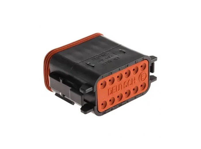
Right angle headers feature pins bent at a 90° angle, standing vertically relative to the PCB surface. These are engineered for compact, stacked ECU housings where internal height is strictly limited. Models like the DT series vertical board connectors allow for efficient cable entry and exit in cramped dashboard or chassis-mounted controllers.
Core Structural Difference Table
| Comparison Item | Horizontal PCB Auto Header | Right Angle PCB Auto Header |
| PCB Occupation | Long horizontal footprint | Narrow horizontal, low height |
| Wire Routing | Parallel along PCB edge | Vertical upward/downward |
| Typical Pin Range | 2P–26P | 2P–24P |
| Mainstream Series | SUPERSEAL horizontal | DT, AMP MCP right angle |
Multi-Dimensional Technical Performance Contrast
PCB Layout & Space Utilization
Horizontal headers suit wide, thin housings, as they utilize the board’s surface area without imposing height restrictions. Conversely, right angle headers are essential for “dense stacking,” such as in ADAS domain controllers, where the vertical clearance between boards is measured in millimeters.
Mechanical & Vibration Reliability
Automotive environments demand high vibration resistance. Horizontal designs often distribute wire-pulling force more evenly across the solder joints. Right angle headers, while compact, may experience concentrated vertical stress during high-frequency vibration, necessitating robust connector housing supports to mitigate potential solder fatigue.
Electrical & Temperature Performance
For high-speed signal integrity, such as in ADAS lines, the choice of orientation can influence trace routing. Both types are engineered to handle the typical vehicle range of -40℃ to 125℃. Stability under thermal cycling is less about orientation and more about the quality of the terminal material and contact plating consistency.
Mass Assembly Cost & Production Efficiency
Horizontal headers are often easier to process on standard SMT lines due to their flat profile. Right angle headers may require specialized jigs for automated insertion to ensure perpendicularity. Large-batch production often favors the orientation that minimizes manual harness dressing time after the board is secured in the housing.
Scene-Based Matching Principles
New Energy & Fuel Vehicle Modules
For BMS mainboards or infotainment systems where side-entry wiring is preferred, horizontal headers are the standard. In contrast, chassis-mounted ECUs that must fit into narrow frame rails perform better with right angle connectors that route wires directly away from the PCB.
Lithium Power Tool & Garden Equipment
Large garden equipment like mowing robots typically has internal space for horizontal configurations. However, handheld tools like trimmers or compact blowers rely on right angle headers to keep the drive PCB as slim as possible, providing users with a more ergonomic tool body.
Step-by-Step Standard Selection Process
Define Housing Envelope: Measure the internal height and horizontal length available in your control module.
Evaluate Signal Requirements: Determine if high-speed ADAS signaling or heavy-duty power circuit transmission is needed.
Assess Vibration Intensity: Chassis-mounted components require different mechanical anchoring than cabin-based sensors.
Confirm Wire Standard: Match the header to your harness, ensuring compatibility with 14–20AWG standards.
Standard Compliance: Always verify that the PCB headers comply with IATF16949 requirements for automotive quality assurance.
Common Layout Failure Risks & Optimization Tips
Hidden Problems of Horizontal Headers
The primary risk is excessive horizontal footprint, which may force an increase in overall housing size. Long, unsupported wiring runs near horizontal headers are prone to interference; you can optimize this by specifying fixed wire clips that secure the harness closer to the entry point.
Hidden Problems of Right Angle Headers
The most common issue is vertical collision risk with internal plastic housing shells. Furthermore, concentrated solder joint stress under vibration can lead to cracking. Optimizing this involves increasing the use of secondary reinforcing locking parts to decouple the wire harness strain from the PCB solder joint.
Conclusion
Selecting the optimal orientation for your PCB headers is a critical engineering decision that balances spatial constraints with long-term reliability. By carefully assessing housing dimensions, vibration profiles, and assembly workflows, you can ensure a robust connection for any automotive or industrial control module. Feel free to contact our engineering team to find the ideal components for your next project.