A power tool can pass a bench continuity check and still develop an intermittent connection after assembly. The wire may be large enough for the current, yet too stiff for the available route. The insulation may carry a suitable temperature rating, yet crack where the handle repeatedly moves it. A terminal may accept the nominal conductor size, yet fail because the insulation diameter or crimp setup falls outside its application range.
These failures begin when electrical, thermal and mechanical decisions are made separately. A power tool wiring harness must carry the real load, fit a compact housing, tolerate nearby heat and keep bending stress away from terminations. This guide reviews these requirements as one installed system.
Define the Tool Conditions Before Selecting Wire
Start with the circuit rather than an AWG chart. Record the supply voltage, continuous current, startup or peak current, duty cycle and total conductor path. Set the allowable voltage drop for the circuit. A short motor lead, a battery connection and a low-current control lead may need different constructions even when they sit in the same housing.
Next, map the harness against the surrounding power tool components. Mark motors, switches, battery contacts, control boards, ventilation paths, housing ribs, screw bosses and moving joints. Note where the harness is clamped, where it crosses an edge and where the enclosure can pinch it during final assembly.
Divide the route into fixed, occasionally moved and repeatedly flexed sections. A service lead does not need the same mechanical design as one that bends whenever the trigger or handle moves. Also record vibration, dust, moisture, oil and abrasive exposure.
| Design input | Why it matters | Evidence to prepare |
|---|---|---|
| Continuous and peak current | Affects conductor loss, terminal loading and temperature rise | Load profile and duty cycle |
| Wire length and allowable voltage drop | Sets the electrical loss available to the complete path | Circuit drawing and voltage-drop limit |
| Ambient and nearby heat sources | Reduces the temperature margin available to wire and contacts | Installed temperature zones and operating conditions |
| Routing and movement | Controls bend radius, abrasion risk and strain-relief geometry | Housing model, photographs or installed sample |
| Market and product requirements | May define approved wire styles, materials and test methods | Applicable specifications and target countries |
Select Wire Gauge as a System Decision
Check current, length and voltage drop together
Wire gauge selection begins with the real load profile. Continuous current affects steady heating. Startup, stall or other peak conditions create shorter, higher loads whose effect depends on magnitude, duration and repetition. A generic current chart leaves these conditions undefined.
Review the complete outgoing and return path when calculating voltage drop. A gauge that works in a short sample can produce unacceptable loss after the routing length changes. Connections add resistance, so conductor calculation covers only part of the current path.
Apply thermal and installation corrections
A conductor in free air releases heat differently from one trapped in a bundle beside a motor. Ambient temperature, airflow, bundle size and duty cycle change the result. State the installation condition behind the gauge decision and use a representative temperature-rise test when available data does not match the tool.
Do not make the conductor larger by default
A larger conductor can reduce resistance, but it also increases outside diameter and bending stiffness. It may exceed the terminal wire range, insulation-crimp range or connector rear-entry space. It can force a tighter bend against the housing or make the harness harder to place consistently on the assembly line.
Select a conductor that meets the approved electrical and thermal limits while fitting the terminal, connector, route and mechanical-life requirement. Verify it against the actual wire and terminal data sheets.
Match Insulation to Heat, Movement and Exposure
Do not select insulation from one temperature number. Check the finished wire for temperature range, voltage rating, wall thickness, abrasion, flexibility, fluid exposure and project-specific flame or market requirements. Use the wire style and manufacturer data sheet.
Separate heat resistance from flex performance
A material that retains electrical properties at a higher temperature may still be too stiff for a repeated bend in a compact handle. Another material may feel flexible at room temperature but change behavior at the lowest operating or storage temperature. Review the complete temperature range at the bend location rather than the maximum number printed on a catalogue page.
Insulation thickness also affects the terminal. Open-barrel terminals grip the conductor and insulation in separate zones. Two wires with the same conductor area can have different outside diameters, which changes how the insulation support closes around the wire. Confirm both conductor size and insulation diameter before releasing a terminal.
Account for abrasion and contamination
Inside a grinder, saw or outdoor tool, the harness may contact ribs, fasteners, moving assemblies or abrasive particles. Identify each contact point and decide whether the route, insulation or added protection carries the abrasion requirement. Sleeving, tape, tubing or a grommet can protect a local area, but each addition increases bundle diameter and may create a new stiff boundary.
For UL-related wire claims, check the specific style, manufacturer and conditions through official UL wire and cable guidance. A mark on a wire does not by itself establish that the complete harness meets the tool specification.
Control Temperature Rise Across the Complete Current Path
Temperature rise extends beyond wire gauge. Heat can come from conductor resistance, terminal and connector contact resistance, and nearby sources such as a motor, switch, battery or power electronics. A cooler conductor cannot correct a poor crimp or a marginal mating contact.
Define measurement locations before testing, including relevant conductor sections, high-current crimps, connector interfaces and nearby heat sources. Record supply voltage, current profile, duty cycle, ambient condition and assembly position so results can be compared.
Use the final housing or a representative thermal fixture. An open-bench harness receives more airflow and may hide enclosure heat. Test the operating mode that produces the most demanding defined combination of current and cooling.
Design Bend Life Around the Actual Motion
Flex life depends on conductor stranding, wire diameter, insulation stiffness, bend radius, routing, supports and termination geometry. Calling a wire “flexible” does not establish its service life.
Separate static routing from dynamic bending
A static bend is formed during assembly and remains in place. A dynamic bend repeats during operation. Occasional service movement sits between those cases. Mark these zones on the drawing because each one needs a different design review. The wire manufacturer’s minimum bend information should be checked first, then confirmed in the installed route.
The first moving bend deserves special attention. If it begins at the terminal exit, connector housing, clamp edge or end of a stiff sleeve, fatigue can concentrate in a short section. Provide enough free length for the wire to form a gradual curve without rubbing another component.
Define a representative flex test
A cycle count needs defined test conditions. State the bend radius, angle, direction, speed, load, temperature and sample mounting. Define electrical and mechanical failure, including an intermittent circuit that appears only during movement.
Inspect where the sample actually bends during the test. A fixture may unintentionally move the stress away from the intended risk area. The test should reproduce the installed stress path rather than demonstrate a favorable laboratory movement.
Match Terminals to the Wire and Connector
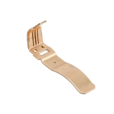
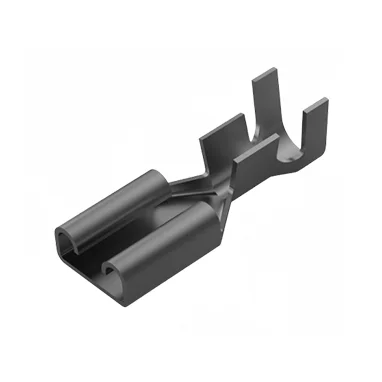
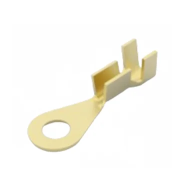
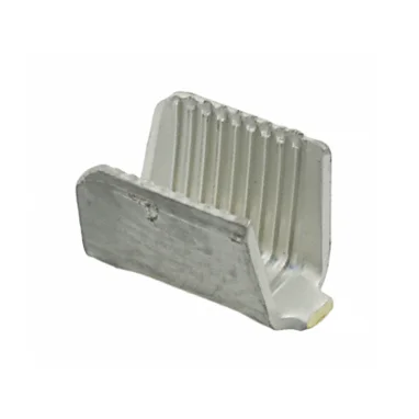
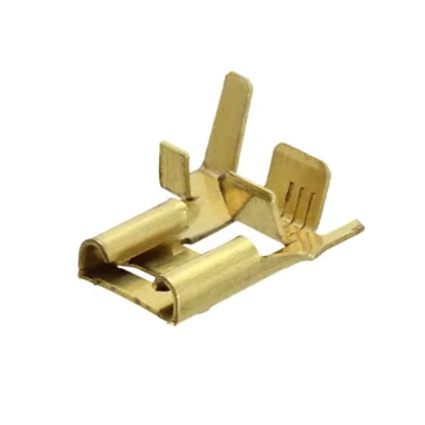
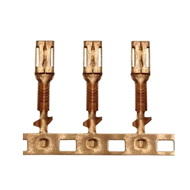
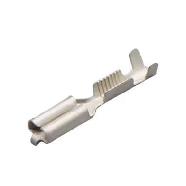
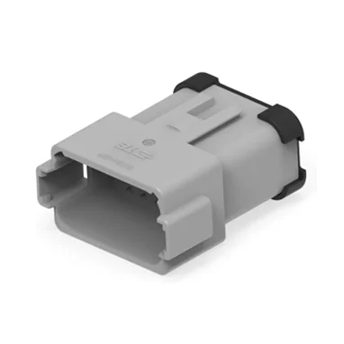
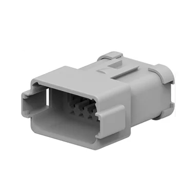
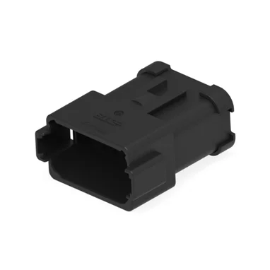
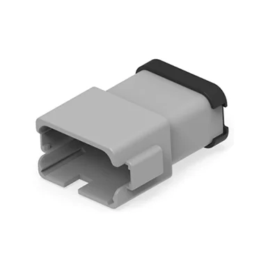
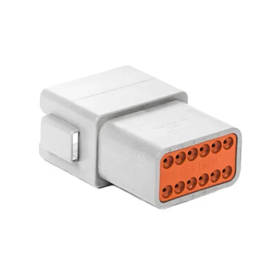
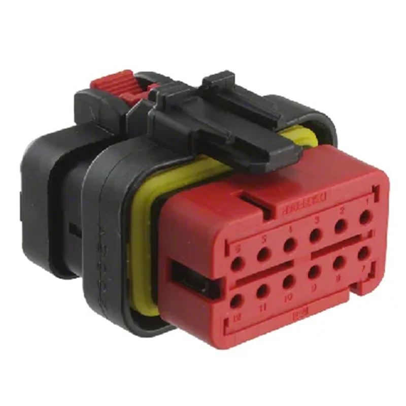
The selected wire terminals must match more than the nominal AWG or square-millimetre value. Check conductor construction, conductor area, insulation outside diameter, terminal material, plating, mating interface, housing cavity and locking feature. Confirm that the terminal supplier supports the proposed combination.
Use the controlled application specification for the exact terminal family. Such documents can define the permitted wire range, strip length, crimp height, insulation support and inspection method. For example, published TE Connectivity application guidance links terminal application to wire and crimp requirements rather than treating the contact as an interchangeable metal part.
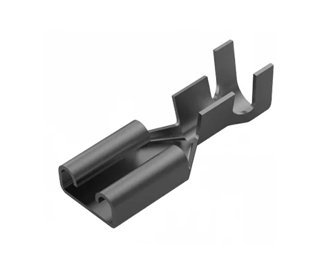
Control the crimp process
The drawing and control plan should identify the terminal, wire, applicator and setup record. Inspect strip length, conductor position, bell-mouth, insulation support and visible strand damage according to the approved specification. Crimp height and pull force can support process control. A cross-section may be required during qualification or process investigation when the project specification calls for it.
Pull force measures mechanical retention under a defined test. It does not prove low contact resistance, correct mating or acceptable temperature rise. Keep those checks separate so that one passing result is not used to cover another failure mode.
Use Strain Relief to Control the Stress Path
Strain relief should move pulling and bending loads away from the conductor crimp and terminal exit. In a power tool, that function may come from a grommet, sleeve, housing channel, clamp, guided loop, heat-shrink part, corrugated tube or moulded feature. The correct method depends on how the harness is installed and moves.
A stiff part can create a new failure point at its edge. A clamp placed too close to the connector can force the first bend into the terminal transition. A loose clamp may allow rubbing, while an over-tight clamp can damage insulation. Review the complete route from the connector through the first support point.
Strain relief also has to be repeatable in production. If its performance depends on an operator placing a cable at an undefined angle, approved samples may not represent volume units. Add critical clamp locations, sleeve positions, free lengths and routing dimensions to the controlled drawing or assembly fixture.
Validate the Installed Harness Before Release
A useful validation plan connects each known risk to a method and a pass criterion. Test names alone are insufficient. State the sample configuration, equipment, conditions, monitoring method and required record.
| Risk | Possible verification | Information to record |
|---|---|---|
| Excessive voltage loss | Voltage-drop measurement under the defined load | Current, path length, voltage and measurement points |
| Conductor or contact heating | Temperature-rise test in a representative tool assembly | Ambient, duty cycle, load, locations and acceptance source |
| Intermittent circuit during motion | Flex or vibration test with electrical monitoring | Radius, angle, direction, rate and failure logic |
| Weak termination | Crimp inspection and specified mechanical test | Wire, terminal, tooling, setup and lot |
| Routing damage | Installed sample inspection before and after operation | Contact points, clamp positions and observed wear |
Release the wire, terminal, connector, protective materials and strain-relief arrangement as one approved configuration. If any item changes, review the effect on crimping, fit, temperature and flex behavior before production continues.
Put the Requirements on the Drawing and RFQ
A quotation cannot resolve missing design inputs. Send the application, circuit or pin table, operating voltage, current profile, allowable voltage drop, wire lengths, routing information, connector details and environmental conditions. Mark requirements that remain open for engineering review.
The released package should identify wire specifications and colors, cut lengths and tolerances, terminal and housing part numbers, strip requirements, protective materials, branch locations, critical bend zones and test criteria. Photographs or a housing model can help explain limited routing space, but controlled dimensions should govern production.
Ask each supplier to return a proposed bill of materials, technical exceptions, substitution list, sample plan, tooling requirements, test scope, minimum order quantity, lead-time breakdown and quotation. Comparable inputs make supplier responses easier to evaluate.
Common Power Tool Harness Design Mistakes
- Selecting wire gauge from a generic current chart without length, duty cycle or installation conditions.
- Increasing conductor size without checking terminal range, connector entry and bending space.
- Choosing insulation from its maximum temperature rating while ignoring movement and abrasion.
- Testing the harness on an open bench while the final housing traps heat.
- Predicting flex life from how soft a sample feels by hand.
- Checking terminal compatibility by AWG but not insulation outside diameter.
- Treating pull-out strength as proof of dynamic strain relief.
- Approving continuity after a flex test without monitoring the circuit during movement.
How GVEI Supports Custom Power Tool Wire Harness Projects
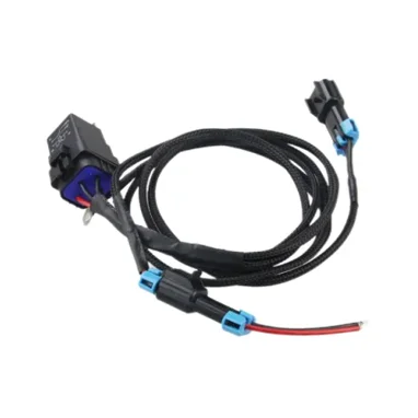
GVEI presents a range of custom power tool wire harnesses for electrical tooling applications. Its current product page states that size, length and connector type can be customized for different tool models. It also describes project-specific test and build boards with revision control for custom assemblies.
Project-specific wire gauge, insulation, temperature and flex requirements still need to be defined and approved for each design. Send the installed conditions and acceptance criteria so the proposed configuration can be reviewed against the tool rather than a generic harness description.
Frequently Asked Questions
How do I choose wire gauge for a power tool wiring harness?
Use the continuous and peak current, duty cycle, total path length, allowable voltage drop, ambient temperature, bundling and available cooling. Then confirm terminal compatibility, routing space and temperature rise in the installed assembly.
Is a thicker wire always better?
No. A thicker conductor can reduce resistance but increase stiffness and outside diameter. It may not fit the terminal, connector or bend space. Select a construction that passes the complete electrical, thermal and mechanical review.
Which insulation material should be used near a motor?
Select from the measured or specified temperature at the wire location, plus abrasion, flexibility, contamination and market requirements. Confirm the exact wire data sheet. A polymer family name alone is not a sufficient specification.
How should bend life be specified?
Define the installed bend radius, angle, direction, rate, temperature, electrical load and required monitoring. A cycle number without these conditions does not establish comparable performance.
How do I match a crimp terminal to the wire?
Check conductor area, stranding, insulation diameter, terminal application range, plating, housing, mating interface and approved tooling. Follow the application specification for the exact terminal family.
Is pull-force testing enough for strain relief?
No. Pull force addresses mechanical retention under its defined method. Dynamic strain relief must also control the bend location and protect electrical stability during representative movement.
Should temperature rise be measured on the wire only?
No. Review conductors, crimps, connector contacts and nearby heat sources. Use defined measurement points in the final housing or a representative thermal assembly.
What should I send for a custom harness quotation?
Send the tool application, drawing or sample, pin table, load profile, wire length, connector requirements, operating environment, movement conditions, test criteria, sample quantity, forecast volume and target delivery date.
Prepare the Design Package for Review
Before requesting a quotation, document where the harness carries current, where it receives heat, where it bends and where it is supported. Include the drawing, load profile, connector and terminal information, available routing space, material requirements and validation criteria.
Ask the manufacturer to return the proposed wire and terminal combination, insulation and protection details, strain-relief arrangement, technical exceptions, sample plan, test scope, tooling, MOQ, lead time and quotation. Send GVEI your power tool harness requirements for a project review.