Piercing terminals face frequent loose contact under vibration and temperature cycles in automotive and power tools. This guide sorts root failure causes and delivers operable prevention schemes for engineers and production teams to cut intermittent circuit faults.
What Is Loose Contact Failure on Piercing Terminals
Loose Contact Failure Manifestations
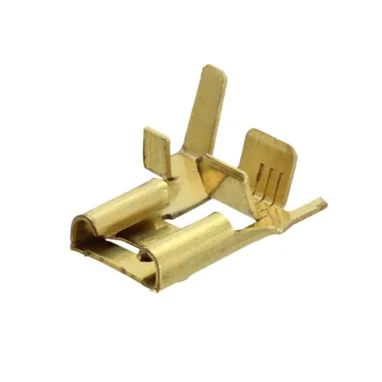
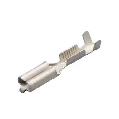
Loose contact in piercing terminals typically manifests as rising contact resistance, intermittent power signals, and localized overheating. Unlike crimp terminals, where the connection is based on a compressed metal barrel, piercing terminals rely on blades to penetrate insulation. A failure here often results in arcing or erratic sensor data, which is especially critical in automotive electronics.

Mechanism Difference: Why Piercing Terminals Are Prone to Loose Contact
The core of the issue lies in the structural mechanics of the insulation-piercing blade. If the bite depth is insufficient, the blade fails to create a gas-tight junction with the conductor. Furthermore, metal spring fatigue—often caused by poor material tempering—can allow the terminal to “breathe” during thermal expansion, creating a gap that invites oxidation.
4 Root Causes Triggering Piercing Terminal Loose Contact
Improper Matching Between Piercing Terminal & Wire AWG
A mismatch between the wire gauge and the terminal slot size is a primary failure vector. If the wire is too thin, the blade lacks sufficient surface area to grip the copper, leading to a high-resistance joint. Conversely, an oversized wire can deform the terminal housing during insertion.
Harsh Operating Environment Damage
Automotive chassis and handheld power tools are subject to extreme vibration. This mechanical stress can cause “fretting corrosion” at the contact interface. When combined with high-low temperature cycling, the material expansion and contraction cycle effectively “walks” the terminal out of a secure position.
Unqualified Terminal Manufacturing & Surface Treatment
The geometry of the blade is everything. Unprecision stamping on piercing blades creates burrs that shred the conductor strands instead of cleanly piercing the insulation. Furthermore, uneven tin plating fails to provide the necessary oxidation barrier, accelerating terminal connection issues.
Non-Standard Assembly & Crimping Process
Even the best component will fail if the assembly process is flawed. Uncalibrated equipment often results in inconsistent piercing depth. Engineers must note that these terminals are generally single-use; attempting to reuse a pierced terminal significantly increases the risk of a loose joint.
Root Cause Quick Comparison Table
| Failure Cause | Loose Contact Risk Level | Typical Application Scenarios |
| Wire AWG mismatch | High | Lawn mower, EV BMS harness |
| Long-term vibration | High | Automotive chassis, hand tools |
| Inferior manufacturing | Medium-High | Low-cost non-standard terminals |
| Irregular assembly | Medium | Small batch manual wiring |
Industry-Targeted Prevention Solutions
New Energy Vehicle & Automotive Piercing Terminals
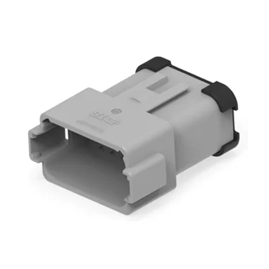
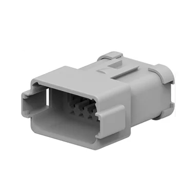
For automotive connectors, anti-loose design is mandatory. By implementing thickened elastic contact shrapnel, the terminal maintains constant normal force despite thermal fluctuations. Rigid production inspection standards for chassis-level wiring help ensure the connection remains stable during road vibration.
Lithium Power Tool & Garden Equipment Piercing Terminals
Tools like mowers or trimmers rely on precision stamping piercing blades with uniform edge profiles to avoid conductor damage. A sharp, uniform blade profile ensures that the connection is made without damaging the internal conductor, while anti-vibration locking structures prevent the housing from backing out during operation.
General Industrial & Telecom Equipment
In humid or industrial cabinet environments, use sealed piercing terminals. A conductive, anti-corrosion coating prevents the ingress of moisture, which is a leading cause of long-term signal degradation in stationary telecom hardware.
Step-by-Step Standard Operation to Prevent Loose Contact
Select Matched Terminals:
Always verify the terminal against the specific AWG range (14–20AWG is the mainstream standard for these applications).
Verify CNC Precision:
Ensure the piercing blades have clean edges before mass production begins.
Calibrate Equipment:
Regularly check crimping force to ensure the standard piercing depth is reached every time.
Conduct Sampling Tests:
Perform pre-delivery resistance and vibration sampling.
Single Use Only:
Strictly prohibit the secondary use of terminals that have already been pierced.
Standard Inspection Items to Detect Hidden Loose Contact Risks
Electrical Testing
Utilize contact resistance threshold detection. A healthy terminal should show stable, low-milliohm readings; any resistance fluctuation data during a gentle vibration sweep is a red flag for hidden loose contact.
Mechanical Durability Test
Subject a sample set to vibration cycle tests and temperature aging. This mimics the lifecycle of a power tool component, validating that the spring force remains within spec.
Visual Structural Inspection
Post-test, use magnification to check for blade wear or terminal spring deformation. If the blade exhibits plating peeling, it is an indicator of inferior material quality.
Conclusion
To avoid loose contact, prioritize precision-machined terminals and standardized crimping processes. By ensuring a perfect wire-to-terminal match, you can guarantee long-term system reliability.
If you need reliable stamping piercing terminals with stable anti-loose contact performance for automotive EV, lithium power tools and industrial wiring harnesses, GVEI provides ODM mold development, customized terminals and full harness assembly. Send your technical drawings to get professional technical support and quotation.