Automotive ECU and EV control integration makes connector selection critical. Many engineers struggle to choose between PCB board end headers and wire-to-wire harness connectors. This guide delivers quantifiable comparisons and scene-based selection rules to help you mitigate failure risks and optimize your production costs for reliable vehicle electronic systems.
Clear Distinction Between Two Connector Types
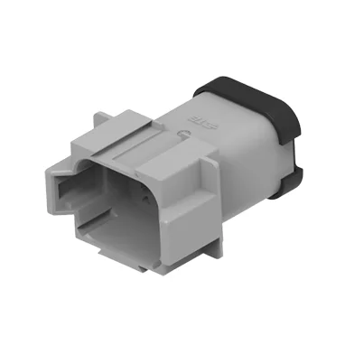
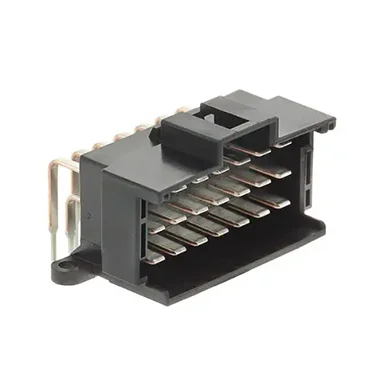
What Are PCB Board End Automotive Connectors (Wire-to-Board Headers)
PCB board end headers, such as horizontal or right-angle THT/SMT configurations, serve as the primary interface for control modules. These automotive PCB headers are soldered directly onto the printed circuit board, creating a fixed bridge between internal microprocessors and external wiring harnesses. They are engineered for high-density integration where space is at a premium.
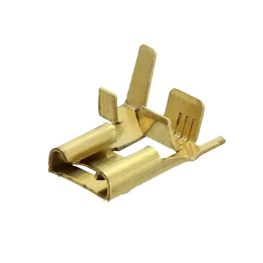
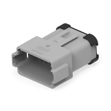
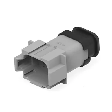
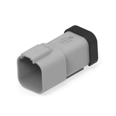
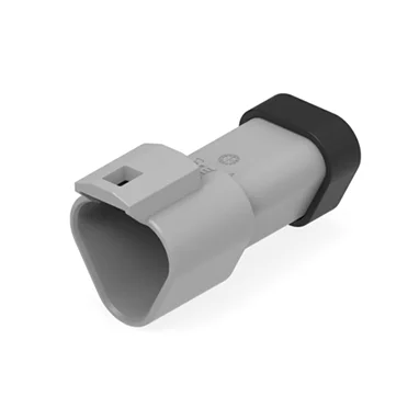
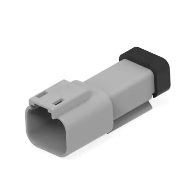
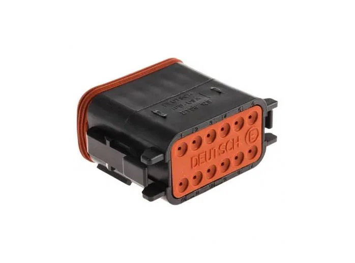
What Are Automotive Wire-to-Wire Harness Connectors
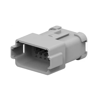
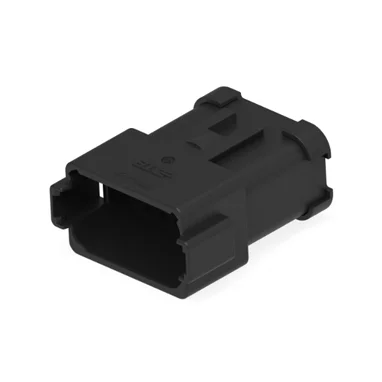
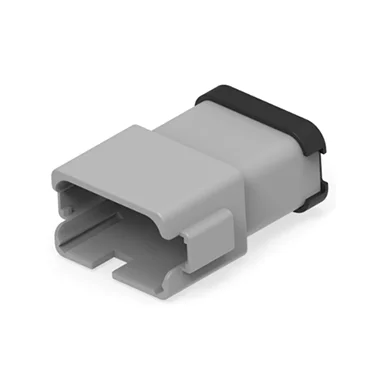
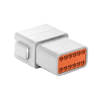
These are free-hanging, plug-and-socket assemblies designed for interconnecting two separate wire bundles. Unlike board-mounted versions, these housings (represented by the DT series) require no PCB layout. They are the standard for linking sub-systems across the chassis, engine bay, or body of a vehicle.
Key Structural Difference Table
| Feature | PCB Board End Headers | Wire-to-Wire Connectors |
| Mounting | Soldered to PCB (SMT/THT) | Free-hanging (Crimp) |
| Space Usage | High density, compact | Requires cable routing space |
| Wire Capacity | Limited by PCB footprint | Flexible, supports thick AWG |
| Key Series | Customized Header Arrays | DT/Superseal Style |
Multi-Dimensional Technical Performance Comparison
Electrical Performance
PCB headers are typically constrained by the PCB’s copper traces. They are ideal for low-to-medium current ADAS signal transmission. Conversely, wire-to-wire automotive connectors handle heavy-duty power distribution for battery packs and drive motors, where the current load would exceed the thermal limits of standard control boards.
Environmental & Mechanical Reliability
Both types must withstand the standard automotive temperature range of -40℃ to 125℃. However, wire-to-wire connectors often offer superior vibration dampening due to their floating contact design. PCB headers, while robust, are susceptible to solder joint fatigue if not properly supported by additional mechanical housing reinforcements.
Assembly & Mass Production Cost
For large-volume production, SMT-ready PCB headers offer significant automation advantages. A pick-and-place machine can mount hundreds of headers in minutes. Wire-to-wire connectors involve more manual labor—crimping, terminal insertion, and housing assembly—which increases the “touch time” per unit in your production line.
Compact Comprehensive Comparison Summary
| Metric | PCB Board End | Wire-to-Wire |
| Current Handling | Low-Medium | High |
| Waterproof Rating | Board-seal dependent | High (IP67/IP69K) |
| Space Usage | Optimized | Extensive |
| Assembly Cost | Lower (Automated) | Higher (Manual) |
Matching Application Scenarios: When to Choose
New Energy EV Scenarios
PCB headers are the backbone of BMS mainboards and ADAS domain controllers where signals must reach the processor directly. Wire-to-wire options are preferred for the main battery-to-inverter harnesses where electrical isolation and flexibility are paramount.
Fuel Vehicles & Construction Machinery
In fuel vehicles, use PCB headers for dashboard ECU internal interfaces to keep the cabin wiring organized. Utilize heavy-duty, sealed wire-to-wire connectors for engine cabin sensors, as they provide better protection against oil, grease, and high-pressure washing.
Power Tool & Garden Equipment
For lithium tool drive boards, compact PCB headers enable the slim design users expect. However, for outdoor equipment like robotic lawn mowers, external harnesses must use wire-to-wire connectors to withstand continuous environmental exposure.
Step-by-Step Guide to Select Suitable Connectors
Analyze Circuit Current:
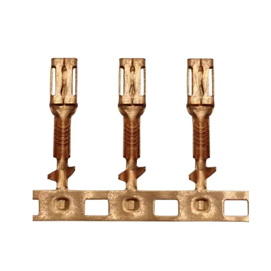
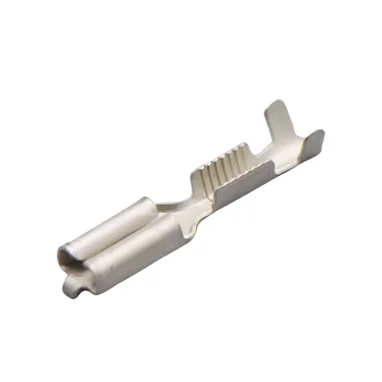
Match your AWG wire requirements. Standard 14–20AWG tin terminals are sufficient for most signal-heavy applications.
Evaluate PCB Layout:
If the control module footprint is restricted, opt for a right-angle PCB header.
Define Environmental Specs:
If the unit sits outside the cabin, prioritize IP67-rated wire-to-wire housings.
Calculate Assembly Labor:
Estimate the time required for harness assembly versus PCB soldering to forecast long-term cost.
Verify Quality:
Ensure your chosen components are produced under IATF16949 standards for consistent supply chain reliability.
Typical Failure Risks & Targeted Optimization
Common Failures of PCB Board End Connectors
The primary risk is solder joint cracking due to thermal expansion or vibration. You can optimize this by specifying thickened tin plating and incorporating secondary mechanical locking tabs that anchor the header to the module housing, not just the PCB pads.
Common Failures of Wire-to-Wire Harness Connectors
Common issues include terminal back-out and seal aging. The fix is to ensure the use of integrated secondary locks (TPA) that prevent the terminal from retreating during high-vibration events.
Conclusion
Selecting the right connector is vital for system durability. By balancing electrical load, assembly efficiency, and environmental requirements, you can optimize both performance and cost. Contact us to find the ideal components for your engineering project.